Close
FEA is a specialized field where study of irregular / complex geometry is performed to evaluate its response under various load conditions. To represent real world objects into FEA we need to build the numerical model in FEA software which will solve the differential equation to give the answers. Deciding on the way the numerical model will be built is called idealization.
We should be very clear on what parameters we want to know as FEA outcome. Some of the guiding parameters can be: Stresses, Displacements, Deformation, Temperature profile, Flow, Velocity, etc.
Also, we need to have some idea of behavior of system under given parameters.
For Example, Consider that we want to analyse this lifting arrangement. If we are using a cotton rope having the strength considerably less as compared to the support Girder (heavy steel section), the girder can be considered as rigid in analysis. But if we use steel rope with comparable strength, then girder can’t be considered as rigid.
The general guideline is to start simple, assume linear behavior build the model, see the pattern and then build further and make it more complex stepwise.
FEA is an approximate numerical method to build the mathematical model which will solve differential equation. So depending on the complexity of numerical equation, the idealization complexity (or extent of simplification) will be decided.
While using commercial software package, this step can be summed up as selection of element model, from the available library of models.
The FEA packages come with a lots of library of built in element models. Have a close look at the elements and decide on the basis of output desired.
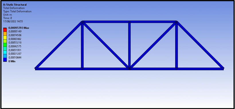
Example 1: To represent Bridge elements, a linear beam element is ideal, it models the out of plane bending correctly while ignoring the axial strain and elongation.
Example 2: Shell elements can be used to represent a thin pressure vessel behavior under moderate pressure by having “thickness” as property. Shell element considers out of plane bending, while
ignoring In plane bending / shear completely.
Example 3: Solid elements are good to evaluate through thickness stresses and deformations, but are not good to represent out of plane bending.
Based on purpose, choose the appropriate element carefully. In general, structural elements will compute displacements, thermal elements will compute temperature, conductivity etc.